Depth Maps for CNC Relief Carving: From Photo to Toolpath
How to prepare a depth map for CNC relief carving: resolution, depth, background, PNG or STL, roughing and finishing tools, stepover and common mistakes.
By Depthue Lab3 min read
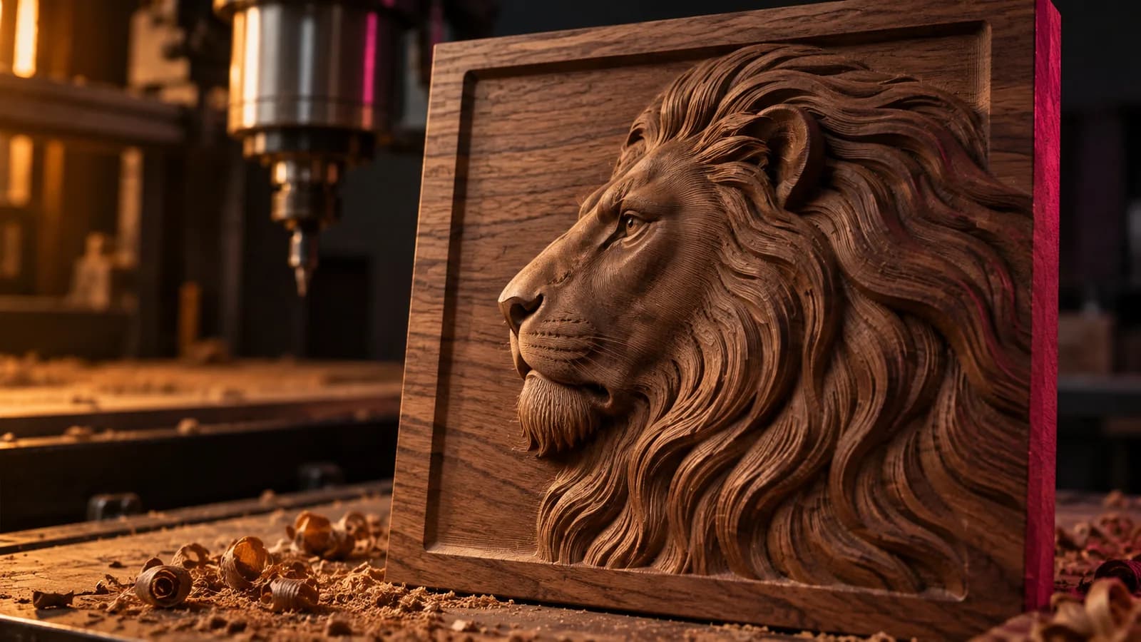
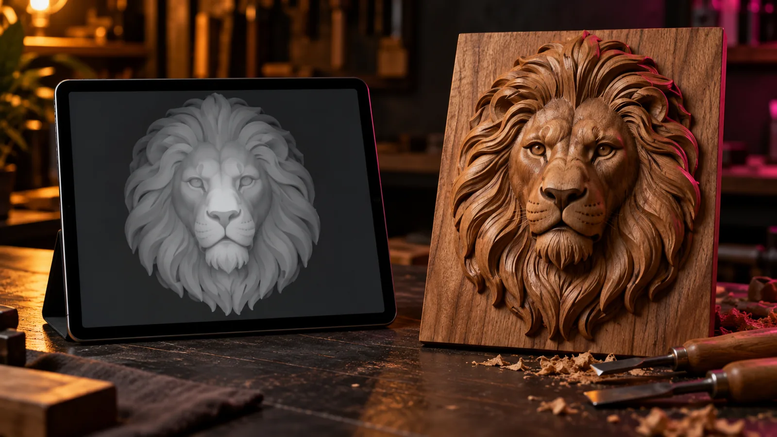
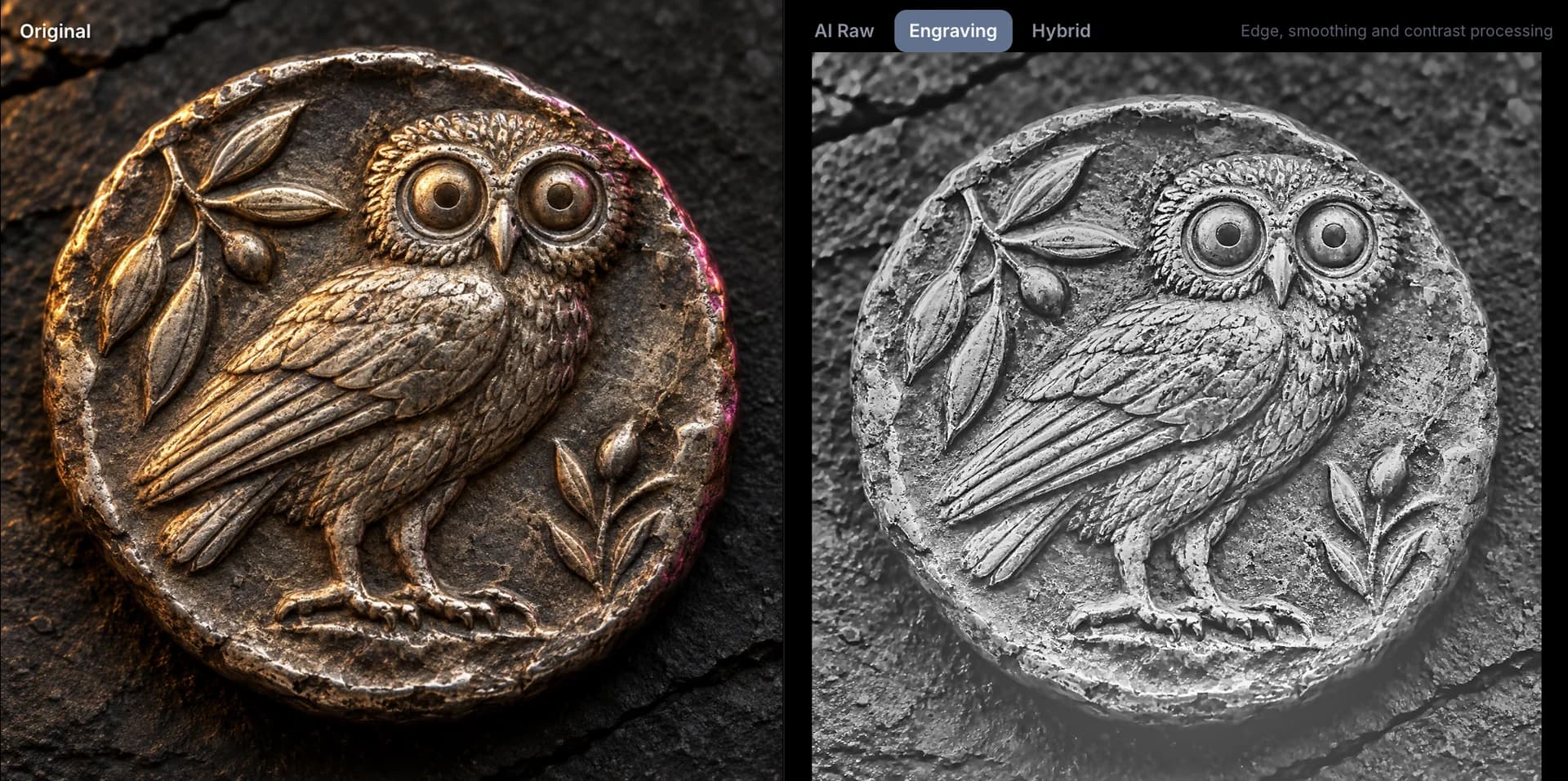
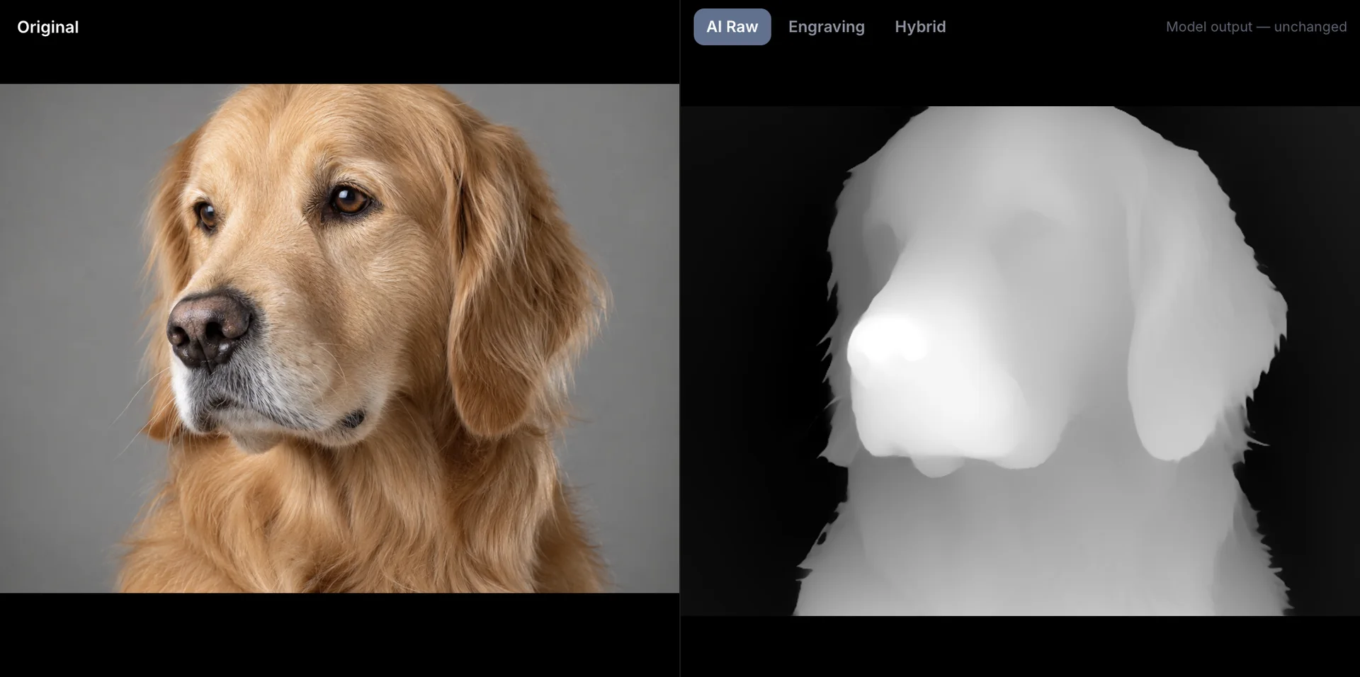
A CNC router cannot read a photograph, but it can read a depth map. The grays become heights: white is the top of the stock, black is the deepest point, and everything between is a smooth ramp. Get the map and the toolpaths right and a photo becomes a carving that catches light like a sculpture.
1. Make a depth map that suits a router
Routers are less forgiving than lasers in one way: they cut real depth with a physical tool. That changes what a good map looks like.
- Flat, black background. Anything left gray becomes a sloped floor the router has to clear. Push the background to pure black.
- Soft transitions. Hard black-to-white steps become vertical walls that a ball-nose tool cannot cut cleanly. A little smoothing helps.
- Detail sized to the tool. A 1.5 mm ball cannot carve detail smaller than about 1.5 mm. Extra pixel detail only slows the job.
- Enough range. Use the full black-to-white range; your CAM sets the physical depth, and a map that only spans mid-grays wastes it.
Make one for free with the depth map generator: raise the black point until the background is black, keep detail modest (15 to 25 percent), and add a little smoothing.
2. PNG or STL?
| Import as | Use when |
|---|---|
| PNG height map | Your CAM builds reliefs from bitmaps and you want to set depth, tilt or combine shapes there |
| STL mesh | Your CAM machines meshes, or you want exactly the relief you previewed |
Vectric Aspire imports a grayscale image as a 3D component and lets you set its height, fade it or combine it with other components. Many other CAM programs work from an STL instead. The image to STL tool and DepthGen Pro both export watertight STL with a solid base at the size you choose.
3. Choose depth and size
A relief does not need to be deep to look deep. Light does the work.
| Piece | Typical relief depth |
|---|---|
| Small plaque or coaster | 2 to 4 mm |
| Portrait panel | 4 to 8 mm |
| Wall piece seen from a distance | 6 to 12 mm |
Keep a margin of material below the deepest point so the panel stays rigid, usually at least 3 mm.
4. Toolpaths: rough, then finish
Roughing removes most of the material fast. Use a flat or a large ball end mill, a stepover around 40 percent, and leave a small allowance (0.3 to 0.5 mm) for finishing.
Finishing makes the surface. Use a small ball nose or a tapered ball nose:
- Stepover: 8 to 10 percent of the tool diameter. Smaller is smoother and slower.
- Strategy: raster at 45 degrees, or two perpendicular rasters for the smoothest surface.
- Feed and speed: see the CNC rows in the settings tool as a starting point for your wood.
Tapered ball bits are a favourite for reliefs because they are stiff enough to reach deep areas without snapping.
5. Mistakes that ruin a carve
- A gray background. The router carves a slope you never wanted.
- Detail smaller than the tool. It disappears, or the tool chatters through it.
- Wrong polarity. If the subject comes out sunk into the wood, the map needed inverting.
- No finishing allowance. Roughing too close leaves steps a finishing pass cannot hide.
- Grain running the wrong way. Raster along the grain for the finishing pass on open-grain woods.
When to use DepthGen Pro
For occasional panels, the free generator is enough. DepthGen Pro earns its place when you carve for customers: it keeps maps offline, lets you brush out model mistakes before you cut, exports 16-bit maps and watertight STL or OBJ, and processes a whole order in one batch.
Free tools for this job
Frequently asked questions
Can I carve a photo on a CNC router?
Yes, as a relief. Convert the photo to a depth map, import it into CAM software as a height map or STL, set the relief depth, and cut it with a roughing pass and a ball-nose finishing pass.
Should I import a PNG or an STL into my CAM software?
Use the PNG when your CAM builds reliefs from bitmaps, as Vectric Aspire does, because you can adjust depth and combine it with other components. Use an STL when the CAM expects a mesh, or when you want the exact geometry you previewed.
How deep should a relief carving be?
For wall plaques 6 to 12 mm of relief reads well from a few metres away. Portraits look natural between 4 and 8 mm. Deeper reliefs need longer tools and more roughing time.
What bit should I use to finish a relief?
A 1/16 inch (1.5 mm) ball nose or a tapered ball nose with a small tip. Tapered bits are stiffer and reach deep areas without breaking, which is why they are popular for reliefs.